Last year I worked on a Vikings teaser for King and Country over in Santa Monica. The spot was mostly live-action, but there were a bunch of CG snakes that needed to be added in post, and so I finally got to flex my rigging muscles a little bit.
First, here’s the spot:
Snakes seem like simple problems to solve, since they don’t have shoulders or hips or any other nasty bits that are hard to rig on humans, but the problem lies within the lack of control an animator has over a typical IK spline.
Most simple snake rigs are just that… make an IK spline, cluster the curve, let the animator sort out the rest. Maybe the animator will get lucky and there will be some kind of control hierarchy, but otherwise they’re in for a lot of counter-animating hell. IK splines also suffer from a lack of precision twisting… snakes (especially when you have big piles of them) tend to need to have different twisting rotations along the length of the body, and IK splines can only twist linearly from start to end. Stretching them also typically results in unstable behavior, with the end joint stretching well beyond the intended values, especially when the spline curve is bent quite a bit.
Click below for more details…
These snakes also needed to be able to easily slither over each other realistically without the animators needing to constantly counter-animate the interaction points. The snakes had to be predictable in their movements so that the animators knew exactly where they were going, e.g. along a path.
The goal for the improved snake rig, then, was to have something that could:
- twist from any point
- stretch in a stable manner ONLY if desired
- move along a path in a predictable way
Problem 1 is often solved by using a Ribbon Spline (sometimes called Ribbon IK). Rather than drive bones using a curve, you can create a NURBS plane, attach hair follicles to it, then parent joints to the follicles. Deforming the plane causes the joints to move and twist along with them, which is great. However, there’s no control over stretching, since you’re actually translating joints on a ribbon, not scaling them. Snakes aren’t particularly stretchy, and if the animator were trying to have the snake move over a particularly complex path with a ribbon setup, she’d have to be extremely careful not to stretch the control points out beyond the original arc length, which is a big pain in the ass.
So to deal with that, I did some poking around and respectfully (blatantly) stole a brilliant idea from David Marte, who posted about a hybrid ribbon/spline IK setup here. Basically, the setup goes like this: Your driving skeleton is still an old-fashioned IK spline. We generate a ribbon geometry from that spline curve, so that it has the same length and parameterization in the U direction (control points are the same along the length of the curve and the ribbon). For each joint in the spline setup, we create a duplicate. We then can take the driver joint from the spline chain, get its position in world space, and find the nearest point on the ribbon to that joint. We can then find the parametric U value of that point on the ribbon, and use that to drive the position of the follicle that the ribbon joint will be parented to. John describes the theory in a little more detail on his page, but those are the basics: get nearest point on the ribbon for each driver joint, convert that to a U parameter relative to the ribbon, then use that to drive the follicles for the ribbon joints (which we will bind the skin to).
Fortunately, there are some magic nodes you can use so you don’t have to do any math or expressions work. The first is the decomposeMatrix node, which will convert local space to world space for any transform. Some people like to use locators and parent constraints for this, but I like having less visible nodes in the DAG, and this evaluates faster than a typical constraint. DecomposeMatrix is easy… just plug the driver joint’s worldMatrix output into the InputMatrix input, and you can output the translate value to another magic node, the closestPointOnSurface node. This node takes a position in space and a NURBS surface, and can output a UV value relative to the surface. We can use the parameterU to directly drive the follicle’s parameterU. Now the ribbon follicles will naturally try to do whatever the spline curve is doing, but with the ability to still deform the NURBS surface for twisting and such, anywhere along the surface.
We then get to problem 2… what if we want this thing to stretch? With the closestPointOnSurface directly driving the follicle, we can’t really stretch this thing even if we wanted to. To alleviate this, we can blend the follicle’s value between the original value at the default position (when we first created the follicles), and the CPOS node’s output value. A blendColors node will do this just fine. We can set the Color1 of the blendColors node to be the original parameterU of the follicle when it was created on the surface (or whatever the default position of that follicle should be), and the Color2 can be driven by the CPOS output. Now if we really want the thing to stretch, we can just use the Blender attribute to blend between the two values.
My snake rig had about 100 joints in it, so doing this setup manually would be a huge waste of time, especially if anything about the rig needed to change. So like anything involving rigging in Maya, we have to script it. Making connections and nodes like this is easy in Python. Here’s a code snippet… it assumes we have a parent group for the follicles referred to here as “follicleGroup” with a float attribute called “stretchy,” along with three matching lists: the driver joints (“joints”), the ribbon joints (“ribbonJoints”), and the follicles (“follicles”). You could easily generate these lists with a script… I’m leaving that part to you.
import pymel.core as pm

for x in range(0,len(ribbonJoints)):
        driverJnt = pm.PyNode(joints[x])
        ribbonJnt = pm.PyNode(ribbonJoints[x])
        foll = follicles[x]
        cpos = pm.createNode('closestPointOnSurface')
        # decomposeMatrix node converts local space to world space for each joint
        decomp = pm.createNode('decomposeMatrix')
        ribbonShape.worldSpace.connect(cpos.inputSurface)
        driverJnt.worldMatrix.connect(decomp.inputMatrix)
        decomp.outputTranslate.connect(cpos.inPosition)
        blend = pm.createNode('blendColors')
        blend.color1R.set(foll.parameterU.get())
        cpos.result.parameterU.connect(blend.color2R)
        follicleGroup.stretchy.connect(blend.blender)
        # output to follicle
        blend.outputR.connect(foll.parameterU)
Now we have the basics down. Problem 3 is going to be the predictable movement. We don’t want the controls to be in a hierarchy, because snakes just don’t move that way, and we want to be able to quickly define a path for the snake to follow so that we don’t have to hand-animate every control for the snake’s motion. So a motion path is the obvious solution, although there are some details we’ll need to figure out in order to make this work the way we want it to.
First, we’ll create a big long path for the snake to follow. Just a long, straight NURBS curve with plenty of divisions. We’ll sit the snake on one end of it. Next, we cluster the curve as usual, then create control objects for each cluster. Now we have something to easily define the path the snake will follow. Assuming that we’ve already made control objects to animate our hybrid ik/ribbon setup, now we run into a problem: how are we going to attach all of those controllers to motion paths? And more importantly, how are we then going to animate all of them?
First the theory, then the code. For each control object that drives the snake, we’re going to want to create a parent group for the control if one doesn’t already exist, in the same position/orientation as the control. This will be our offset group, so that we can animate the controls along the path and still be able to set keyframes on the controller itself for fine detail. Next, we’re going to attach the offset group to the big path curve via a motion path. We don’t want the offset group to move at all, though, so we need to figure out where the offset group is in world space, relative to the curve. Sounds familiar? The process is almost exactly the same as how we derived world space transforms via the decomposeMatrix node, except this time we’re feeding that transform information into a nearestPointOnCurve node. We can then take the NPOC node’s parameterU value, and set the motion path’s U value to match. Afterwards we can discard the NPOC node… we don’t need it beyond getting that initial value.
Now we need to set limits. If we didn’t have minimums or maximums for each of these motionPath nodes, then the snake controls would bunch up at one end of the path or the other if the uValue of the nodes were too high or too low. We can figure out what these limits would be based on the current uValue of each path. The minimum value for each path would be its current value (its current parameter U along the curve), assuming the snake is positioned at the very beginning of the path curve already. The maximum value would be its current value, plus the complement of the uValue of the motion path furthest along the chain (the maximum uValue, or maxU). In shorthand, the range is (u, u+(1-maxU)).
Now for some code.
import pymel.core as pm

def smartAttachToMotionPath(curve,targets):
    # for each target, get the closest point on the curve's U value.
    # create a motion path for each and set the u parameter to match the current value.
    # use a +/- node as an offset channel so that min u = current value and max = 1-current value.
    # pipe result into motion path u value.
    # then connect the allCoordinates to translate of each target, and rotate to rotate.
    curveShape = curve
    try:
        curve.type()
    except:
        curve = pm.PyNode(curve)
    if curve.type() == 'transform':
        curveShape = curve.getShape()
    elif curve.type() != 'nurbsCurve':
        pm.error('The first parameter must be a NURBS curve!')
        return False
    maxU = 0
    for target in targets:
        try:
            target.name()
        except:
            target = pm.PyNode(target)
        # create a motionPath offset group that matches the target. attach to motion path.
        # then parent target under offset group.
        origParent = target.getParent()
        offsetGroup = pm.group(em=True,n=target.name()+'_mpOffset')
        pm.parent(offsetGroup,origParent)
        pc = pm.parentConstraint(target,offsetGroup)
        pm.delete(pc)
        mp = pm.createNode('motionPath')
        curveShape.worldSpace.connect(mp.geometryPath)
        npoc = pm.createNode('nearestPointOnCurve')
        curveShape.worldSpace.connect(npoc.inputCurve)
        decomp = pm.createNode('decomposeMatrix')
        offsetGroup.worldMatrix.connect(decomp.inputMatrix)
        decomp.outputTranslate.connect(npoc.inPosition)
        # get u parm
        u = npoc.result.parameter.get()
        # store maxU. this will help us set min/max for attributes later.
        if u > maxU:
            maxU = u
        # add motion path attr to target
        offsetGroup.addAttr('pathU',k=1)
        offsetGroup.pathU.set(u)
        offsetGroup.pathU.connect(mp.uValue)
        # connect motion path output to target
        mp.allCoordinates.connect(offsetGroup.translate)
        mp.rotate.connect(offsetGroup.rotate)
        mp.follow.set(True)
        # parent target to offsetGroup
        pm.parent(target,offsetGroup)
        # cleanup
        try:
            pm.delete(npoc)
        except:
            pass
        try:
            pm.delete(decomp)
        except:
            pass
    # set min/max for each target's pathU attr.
    for target in targets:
        offsetGroup = target.getParent()
        u = offsetGroup.pathU.get()
        offsetGroup.pathU.setRange(u,u+(1-maxU))
Now we can have a single channel animate from zero to one, which directly outputs to all of the motion paths at once. The snake can move along the predefined curve just by keying one channel. Great! But not finished. Right now the snake moves like this:
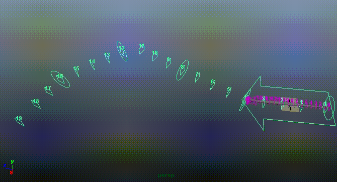
Which is adorable and all, but snakes don’t move like that. We’re totally missing the slither. We could ask the animators to key that in, but that’s a huge pain in the ass. Instead, what we want is to automate a little bit of that slithering into the motion.
In the past, people have done this with carefully-placed sine deformers that bend the motion path, but this is both difficult to control properly and only bends along a single axis, which is not really all that useful. We want the snake to slither relative to the direction that the curve is facing, at any point along the curve. The controllers that drive the snake are already more or less aligned to the curve since they’re on a motion path, so we’re partially there, but what we need to do is figure out how to translate these groups (more specifically, another offset group parented between the controller itself and the existing offset group) to get the sine motion. Let’s just look at a picture real quick:
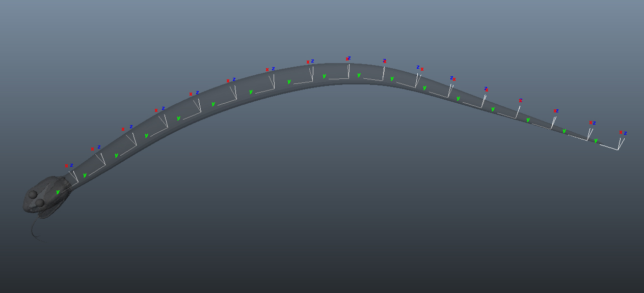
Those axes are those of the controllers we’re dealing with. See how the X axis is always pointing directly normal to the curve (perpendicular to the tangent)? That’s the direction we want to move these offset groups in. We can determine how far we want to translate each group in X based on a sine function. Better yet, since we already have a parameterized curve (the big motion path driving the controllers), we can use that as the basis of our sine function. We take the sine of (uValue * arbitrary frequency) for each controller’s motion path object, multiply it by some value for amplitude, and we have snake motion!
The catch here is that vanilla Maya doesn’t have any way to calculate a sine function in the DAG. We could use expressions, but those are horribly slow to evaluate, especially in large groups, and one of my snakes has 16 or so of these controls to push around. Running expressions for two dozen snakes would be 16 x 24 = 384 expressions to calculate on every DAG update. Let’s not do that.
Instead, we’ll use a free plugin from Autodesk Labs called the Math Node. It takes three inputs, A B and C, and can read simple expression syntax using A B or C as variables, then output a value. It’s not terribly fancy, but all we need is a sine function. You can download the Math Node plugin here.
Assuming that we’ve created another offset group between the control object and the motion path offset group (we’ll call this one “sineOffset”), we just have to take each motion path’s uValue, then find the sine of (uValue * a frequency constant), then multiply that result by an amplitude value. The result plugs into the translateX of each sineOffset group.
Here’s some code:
def motionPathSineOffset(curve,targets,axis='x'):
    # assuming that each target is attached to a motion path based on "curve",
    # make a "sine offset" transform inserted into the hierarchy underneath the target.
    # use that curve and the parent group's uValue to drive a sine offset along the given axis.
    # channels added to curve: sineAmplitude,sineFrequency,sineOffset
    # each parent group gets a sineScale for per-control offset
    try:
        curve.name()
    except:
        curve = pm.PyNode(curve)
    # add control channels to controller and curve.
    curve.addAttr('sineAmplitude',k=1)
    curve.addAttr('sineFrequency',k=1)
    curve.addAttr('sineOffset',k=1)
    for target in targets:
        # convert to pynode if necessary
        try:
            target.type()
        except:
            target = pm.PyNode(target)
        # insert new sine offset group into hierarchy
        children = pm.listRelatives(target,c=1)
        offsetGrp = pm.group(em=1,n=target+'_sineOffset')
        pc = pm.parentConstraint(target,offsetGrp)
        pm.delete(pc)
        pm.parent(offsetGrp,target)
        controller = False
        # find the lowest child in the hierarchy that's a transform...?
        for child in children:
            pm.parent(child,offsetGrp)
            # get child that is actual controller object (parent of NURBS shape)
            # once we find it, set "controller" to this object
            for c in child.listRelatives(ad=1):
                shapes = c.listRelatives(s=1)
                if shapes:
                    for s in shapes:
                        if s.type() == 'nurbsCurve':
                            controller = c
                            break
        controller.addAttr('sineBlend',k=1)
        controller.sineBlend.set(1.0)
        # connect controls to adskMath node, set up sine expression.
        # then connect output to offsetGrp's translate axis.
        pma = pm.createNode('plusMinusAverage')
        md = pm.createNode('multiplyDivide')
        math = pm.createNode('asdkMathNode')
        target.pathU.connect(pma.input2D[0].input2Dx)
        offsetMult = pm.createNode('multiplyDivide')
        curve.sineOffset.connect(offsetMult.input1X)
        offsetMult.input2X.set(0.01)
        offsetMult.outputX.connect(pma.input2D[1].input2Dx)
        curve.sineAmplitude.connect(md.input1X)
        controller.sineBlend.connect(md.input2X)
        pm.connectAttr(md.name()+'.outputX',math.name()+'.aIn')
        pm.connectAttr(curve.name()+'.sineFrequency',math.name()+'.bIn')
        pm.connectAttr(pma.name()+'.output2Dx',math.name()+'.cIn')
        pm.setAttr(math.name()+'.expression','sin(c*b)*a',type='string')
        pm.connectAttr(math.name()+'.result',offsetGrp.name()+'.t'+axis)
If you’re wondering what that multiplyDivide node is doing in there, it’s just to help scale things down so that the offset value is more easily scrubbed in the channel box. The sineBlend attribute is added so that each control can scale down how much slither it receives from the main slither channel.
Now when we animate this guy, it looks like this:
Look at all that free slithering motion! That’s just one animated channel, plus a few static channels to aim the path and set the amplitude and frequency of the sine wave.
This went on way longer than I intended, but hopefully it’s an interesting primer on both spline rigging in general, and on how to automate parts of rigs without taking away controls from the artist. I can’t post the rig for obvious reasons, but if you’re trying to do this yourself and running into a snag, let me know and I might be able to help you.
Good luck!