Those of us unlucky enough to be rendering stills for print are familiar with the idea of rendering tiles in order to allow a render job to be more easily parallelized. Instead of trying to render and save one massive 20k square image to disk from a single machine, bucket by bucket, you can render out the image in chunks, ideally on multiple machines, and then stitch them together after the fact. Some render engines, like VRay, have built-in controls to break apart a scene into tiles to be rendered via Deadline or some other render manager. Others… don’t. Redshift being one of the latter, and the current render engine of choice for myself and many other artists who don’t have access to a huge CPU farm, I had to figure out a way to get some seriously huge images (about 24k x 30k pixels) rendered and stitched together, including render passes, in a real hurry to meet a looming deadline. A couple late nights and an enormous amount of cursing later and I have something working, so here’s how it’s all put together!
Redshift’s not-really-cropping command
Redshift is capable of region rendering (sort of), but it’s only easily controlled via the command line. The command line renderer can be really convenient, but it’s really annoying to write out the commands by hand, and so you typically need some kind of dispatcher to handle this for you. No such thing exists currently for Redshift, so I had to write my own.
The syntax for executing a render from the command line looks like this:
redshiftCmdLine /path/to/rsproxy.rs -ores 1920x1080 -crop 0 0 960 540 -oip /path/to/outputImage
So to make this work for a tiled image, you’d have to write up each of these commands, with the correct crop offsets and dimensions for each tile. If you look at that first argument in the command, you’ll realize you also have to dump your scene to a Redshift proxy file first. This can be pretty easily automated with Python, and is more or less what Deadline’s tiled render submitter for Redshift is doing under the hood. There are of course some gotchas… if you define a crop region that is even a single pixel beyond the bounds of the total output resolution, Redshift will go through all the trouble of rendering your whole tile, and then just refuse to write the image at the end. No warnings, no errors, just “I guess you didn’t want this image after all, idiot!” And then, even worse…
Redshift isn’t actually cropping these output images. It’s just region rendering. So if you’re trying to render out 5×5 tiles of a 10k x 10k image, even though Redshift will only render 2k pixel tiles for each image, it’s still going to output 10k images to disk. Except now you have 25 10k images instead of one, and for each of these tiles, Redshift has to hold all of those pixels in the output buffer in your CPU memory, completely defeating the purpose of tiled rendering in the first place. For an approximately 20k by 35k image I was trying to render, each tile was consuming all 64 GB of RAM on my machine and more, forcing me to commit a much bigger chunk of my disk to swap. The render speeds were very quick per-tile, but writing the files to disk (even with compression) took forever. It was a total waste of time.
I’m not salty at all.
I needed a new solution in a real hurry, and so after testing a few camera attributes in Houdini, I realized Redshift was at least compatible with Houdini’s Screen Window X/Y and Screen Window Size camera parameters. This meant it would be possible to automatically generate a camera array based on the desired tile count, have each camera write to a separate image, and then stitch those tiles back together at the end for the full resolution image. That said, there were potentially a lot of tiles to go through, and I also needed to have the individual render passes properly tiled so that I could layer them up in a Photoshop file for the final deliverable, and there was absolutely no way I was going to sit there and do it by hand because I’m lazy and stubborn and that’s just boring. Plus I was rapidly approaching the deadline and would probably have not been able to get all those passes for each tile stitched in time.
So, time to automate this!
Building the camera array
The first step in automating this process is building up the array of cameras for rendering… one for each tile. (If you’re only rendering stills, you could just keyframe a single camera, but avoiding keyframes here makes it possible to render tiled sequences, in case you really hate yourself.) The cameras then need to be offset using their Screen Window X/Y and Screen Window Size parameters. The exact values for these numbers took me way longer than I’d like to admit to figure out. It’s easier to show visually how Houdini interprets these values than it is to just write out the formula.
For each tile we want to build, we find that tile’s center point relative to the full screen frame, in NDC space (meaning, lower left is 0,0, upper right is 1,1). We then convert that to a -1,1 range, and then scale that down by half. The output coordinates produced will work for any tiling arrangement:
Now that the concept is out of the way, we can start thinking about how to code it in a loop. Anytime you’re programming a grid of something, you’re probably going to be dealing with nested for loops. We’ll iterate over each tile in X, for each tile in Y in order to build our array of tiles.
for y in range(0, ytiles):
    for x in range(0, xtiles):
        zoomx = 1.0 / xtiles
        zoomy = 1.0 / ytiles
Those zoomx and zoomy variables are telling us what the Window Size parameter needs to be for the camera, but they’re also going to help in figuring out what the center coordinate for each of these tiles is. If you can imagine breaking each of these tiles in half while you’re looping over each tile in X, the center of each tile is at that halfway point. Relative to the full camera space, this means that the center of a tile is equivalent to our current tile’s X index, multiplied by the zoom value (1/xtiles), plus half the zoom value (the halfway point of our current tile). Once we have the center point relative to the space of the full camera, we can then map the range to -1, 1 and then scale by 0.5:
def fit(input, oldmin, oldmax, newmin, newmax):
    return (((input - oldmin) * (newmax - newmin)) / (oldmax - oldmin)) + newmin

# get center points relative to original camera
centerx = (float(x) * zoomx) + (zoomx / 2)
centery = (float(y) * zoomy) + (zoomy / 2)
# map center points to scaled space
nx = fit(centerx, 0, 1, -1, 1) * 0.5
ny = fit(centery, 0, 1, -1, 1) * 0.5
Those ending coordinates there, nx and ny, are the Screen Window X/Y coordinates for each camera we’re going to generate. Now what we want to do is actually copy an existing camera and set these offset values for each camera accordingly. In order to make the camera’s transform easier to deal with, we’ll use a Fetch Object to grab the camera’s transform and use it as the parent for each duplicate camera, then zero out the translate and rotate channels so that they match the original camera’s transform exactly. We’ll also need to make a new ROP for each of these copies, based on some original ROP that we’ll duplicate. It’ll keep the scene clean to put all of these objects under a subnetwork that we’ll call “root” in this code.
We’ll want to ensure that each camera (and the associated ROP and output file path) is named in a way that reflects the tile coordinates. This will help later on when we’re trying to automate the stitching process. One option would be UDIM tiles, which is a standard for texture maps. A UDIM is a four-digit number, where UDIM = 1001 + x + (y * 10). It’s a nice convention and makes sorting very straightforward, but it comes with the downside that you can only have a maximum of 10 horizontal tiles. For flexibility, we’ll use the more Mudbox-y image_u##_v## convention instead.
import hou
import os

def fit(input, oldmin, oldmax, newmin, newmax):
    return (((input - oldmin) * (newmax - newmin)) / (oldmax - oldmin)) + newmin

def tile_camera(camera_path, rop_path, xtiles=2, ytiles=2, parent_obj="/obj"):
    root = hou.node(parent_obj)
    if root is None:
        root = hou.node("/obj").createNode("subnet", "CAMERA_TILES")
        root.setDisplayFlag(False)
    cam = hou.node(camera_path)
    fetch = root.createNode("fetch")
    fetch.parm("useinputoffetched").set(1)
    fetch.parm("fetchobjpath").set(camera_path)
    fetch.setDisplayFlag(0)

    # get node reference to original rop
    rop = hou.node(rop_path)

    # create ropnet
    ropnet = root.createNode("ropnet", "TILE_OUTPUTS")
    output = ropnet.createNode("merge", "OUT")

    for y in range(0, ytiles):
        for x in range(0, xtiles):
            # duplicate camera and reset transform.
            newcam = root.copyItems([cam], channel_reference_originals=True)[0]
            newcam.setInput(0, fetch)
            # clear channel references for things we have to modify
            newcam.parm("winx").deleteAllKeyframes()
            newcam.parm("winy").deleteAllKeyframes()
            newcam.parm("winsizex").deleteAllKeyframes()
            newcam.parm("winsizey").deleteAllKeyframes()
            zoomx = 1.0 / xtiles
            zoomy = 1.0 / ytiles
            newcam.parm("winsizex").set(zoomx)
            newcam.parm("winsizey").set(zoomy)
            # clear transform channel references.
            # looping this way is shorthand for clearing and setting parameters for 'tx', 'ty', 'tz', etc.
            for ch in ['t','r']:
                for dim in ['x','y','z']:
                    newcam.parm(ch+dim).deleteAllKeyframes()
                    newcam.parm(ch+dim).set(0)

            centerx = (float(x) * zoomx) + (zoomx / 2)
            centery = (float(y) * zoomy) + (zoomy / 2)
            nx = fit(centerx, 0, 1, -1, 1) * 0.5
            ny = fit(centery, 0, 1, -1, 1) * 0.5
            newcam.parm("winx").set(nx)
            newcam.parm("winy").set(ny)

            # now set camera resolution to be a single tile width.
            orig_resx = cam.evalParm("resx")
            orig_resy = cam.evalParm("resy")
            newcam.parm("resx").deleteAllKeyframes()
            newcam.parm("resy").deleteAllKeyframes()
            newcam.parm("resx").set(orig_resx / xtiles)
            newcam.parm("resy").set(orig_resy / ytiles)

            # set camera name
            tilenum = "u{}_v{}".format(str(x).zfill(2), str(y).zfill(2))
            newcam.setName(cam.name() + "_{}".format(tilenum), True)

            # duplicate rop and set camera
            newrop = ropnet.copyItems([rop], channel_reference_originals=True)[0]
            newrop.setName(cam.name() + "_{}".format(tilenum), True)
            newrop.parm('RS_renderCamera').deleteAllKeyframes()
            newrop.parm('RS_renderCamera').set(newcam.path())

            # set output to match input, with UVtile as containing directory
            outpathparm = rop.evalParm("RS_outputFileNamePrefix")
            outpath = os.path.join(os.path.dirname(outpathparm), newrop.name(), os.path.basename(outpathparm)).replace("\\","/")
            newrop.parm("RS_outputFileNamePrefix").deleteAllKeyframes()
            newrop.parm("RS_outputFileNamePrefix").set(outpath)

            # ensure that the ROP dependencies will actually properly render with redshift
            newrop.parm("RS_nonBlockingRendering").deleteAllKeyframes()
            newrop.parm("RS_nonBlockingRendering").set(0)

            # merge with ROP network's output
            output.setNextInput(newrop)
    # cleanup
    root.layoutChildren()
    ropnet.layoutChildren()
This is a bit of a mouthful, but it’s essentially creating a neatly-packaged container that all of our duplicate cameras and ROPs will live in, determining their tile number based on where we are in the loop, creating the duplicate cameras, parenting them to a Fetch OBJ that keeps them locked to the original camera’s transform and zeroing out any existing transform, setting their scales and window offsets based on the formula described above, then generating a ROP to go along with each camera. The ROP is set to render from their respective camera, and the original ROP’s render path is modified so that each tile is placed into a folder with the tile’s UV coordinates spelled out. We’ll need this information later when we’re handling the stitching operation. Finally, each ROP is wired to an output Merge ROP so that all the tile renders can be submitted at once. To run the function, paste it into the Python Source Editor and then follow with this:
tile_camera("/obj/cam1", "/out/Redshift_ROP1", 4, 4, "/obj/CAM_TILES")
The first argument is the source camera, followed by the source ROP. The next two are your tile count in X and Y, and the last is a path to a parent subnetwork to put all the duplicate cameras and ROPs into. The nice thing about handling it this way is that if there’s anything wrong with the generated cameras we can just delete the whole parent subnetwork and try again, and all of the camera and ROP settings are based on the master camera and ROP.
Before you render that ROP, another fabulously dumb thing about Redshift that is not well-explained anywhere: if you merge Redshift ROPs together, they will not render aside from the last ROP in the chain unless you disable the “Non-Blocking Current Frame Rendering” parameter under Redshift > Main. In the code above, I’ve ensured that this is disabled on the duplicate ROPs, but it’s something (stupid) that you should be aware of when setting up dependencies in Redshift.
Another setting to pay attention to here is the multichannel / layered EXR settings. Since we’re going to use ImageMagick to deal with stitching these huge images, it’s best to keep AOVs separate. It’ll keep any one image from getting too enormous and maxing out RAM during that process (unless you’re going really, really big).
Just select that resulting ROP and render it to disk, and now we can get to the “fun” part: TOPs.
Stitching the tiles in TOPs
Full disclosure: I don’t like TOPs. It’s clumsy and unintuitive, it’s way too easy to fail to set dynamic versus static workitems, it sometimes works perfectly and then fails without any sort of logged reason the next time you cook your network. The whole thing feels completely arcane, and not in the lovable way the rest of Houdini feels arcane.
Now that that’s out of the way, TOPs is still the perfect way to stitch all of these things together, assuming you don’t want to write your own Python subprocess to handle it for you. It’s still going to require a fair bit of Python, though, because we need to be able to recognize the individual render passes, and that means our old pal regular expressions. Get ready for some Type II fun!
First, drop down a TOP network and create a File Pattern TOP. These handy nodes will hunt down all of our image files within a parent directory. Just point it to the directory where all the tile folders are and enable “Recursive” to find them all. You can use glob-style matching to find files with specific names or extensions… in my case, I’m setting the pattern to $HIP/render/*.exr.
Next, an Attribute Create TOP. This is often how I’ll add attributes to my TOPs workitems that I can control later through a user interface. I’m creating one string attribute called outdir and setting it to my output destination for the stitched renders, $HIP/stitched/. (I’m not putting it inside $HIP/render/ because if I had to run this process again, it would pick those files up and break everything.) I’m also going to add a prefix string attribute and just set it to “stitched” for now… this will be the name of the output images (followed by the render pass for each).
Before we get to our first big ugly Python script, if you’re not used to working with TOPs, you might be wondering what the hell we’re actually making here. Where in SOPs you have points, in TOPs you have workitems. Some TOPs generate workitems, some modify them, some collapse them into groups of workitems called partitions and some expand partitions back to workitems. Workitems have attributes just like SOP points do. You won’t see any workitems at all, though, until you generate them. You can right-click any TOP along the chain to generate, and/or cook, the workitems. Once you do that here, the File Pattern TOP will generate one workitem for every file it discovers, and the Attribute Create TOP will add our outdir and prefix attributes to each one. Right-click the Attribute Create and select “Cook Selected Node”, and you’ll see a bunch of green dots appear on your TOPs, one for each file. Double-click a dot and you’ll get a list of attributes:
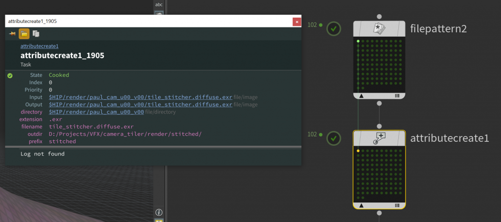
The attributes (so far) of a single workitem.
In addition to the attributes we created, there’s filename, directory, and extension, that we get from the File Pattern TOP. There’s also input and output, which are currently set to the full path on disk. These are special attributes that many TOPs expect to see when dealing with any operation that runs on files or paths. We’ll need to pay special attention to them soon.
Parsing the filenames
Now time for some scripting. The Python Script TOP runs Python over your workitems. This is handy for generating new attributes with values that can’t be set simply by user input. In this case, we want to figure out two things: what render pass each image we found belongs to, and what UV tile each image represents. For the render pass, we’ll create a new string attribute to store it to, and for the UV tile we’ll create an integer attribute. In TOPs, all attributes are inherently arrays (I think?) so our UV attribute will act like an integer array (u, v).
Now the really ugly stuff. Our renders coming out of Redshift, in this case, are going to be followed by the render pass name, and then the file extension, both preceded by periods. The beauty pass (the primary framebuffer) doesn’t have any pass at all, though, so we need a regular expression to search for this pass (if it exists) and then store it to a match group. I don’t really want to go into the guts of regular expression in this post… they’re great, but they’re also horrific to look at and hard to explain. Here’s the regex to parse the render pass from a filename that may or may not have one:
RS_IMAGE_REGEX = "^[\w]+[\.]?([\w]*?)[\.]\w{3,4}$"
Ew. What I’m telling the parser to do here is look for a bunch of alphanumeric characters, I don’t care how many, followed by a period (maybe? hence the question mark), followed by another alphanumeric string (maybe?) followed by a period, and then three or four characters (the file extension), and then that’s the end of the string. The maybe-alphanumeric-string is inside parentheses, which indicates that it’s a “capture group” and I want to store its value for later.
The second thing we need to parse are the UV tiles from the parent folders. This is a bit more straightforward, though the regex is no less hideous:
UV_REGEX = "^[\w]+_u(\d{2})_v(\d{2})$"
What we’re doing here is looking for a bunch of alphanumeric characters and then promptly ignoring them, followed by _u##_v##, and then that’s the end of the string. The numbers after _u and _v are sent to capture groups so we can use them later.
Anyways, here’s the whole script:
import os
import re
import sys

RS_IMAGE_REGEX = "^[\w\-\.]+?[\.]?([A-Za-z]+[\w]*?)[\.]\w{3,4}$"
UV_REGEX = "^[\w]+_u(\d{2})_v(\d{2})$"
# parse renderpass name and add as string attr
passname = re.match(RS_IMAGE_REGEX, work_item.attribValue("filename"))
if passname:
    passname = passname.group(1)
    if passname:
        pass_attr = work_item.addAttrib("renderpass", pdg.attribType.String)
        pass_attr.setValue(passname)
    else:
        pass_attr = work_item.addAttrib("renderpass", pdg.attribType.String)
        pass_attr.setValue("beauty")
dir = work_item.attribValue("directory").path
tilename = os.path.basename(dir)
# parse the tilename into U and V ints
tiles = re.match(UV_REGEX, tilename)
u = None
v = None
if tiles:
    utile = tiles.group(1)
    if utile:
        u = int(tiles.group(1))
    vtile = tiles.group(2)
    if vtile:
        v = int(tiles.group(2))
if u is not None and v is not None:
    tile_attr = work_item.addAttrib("uvtile", pdg.attribType.Int)
    tile_attr.setValue(u, 0)
    tile_attr.setValue(v, 1)
In the above script, we’re grabbing the render pass name from the file if it exists, and defaulting to “beauty” if it doesn’t, then getting the UV tile name, and storing both to workitem attributes that we create on the fly. Here’s what the attributes of the newly generated workitems are going to look like:
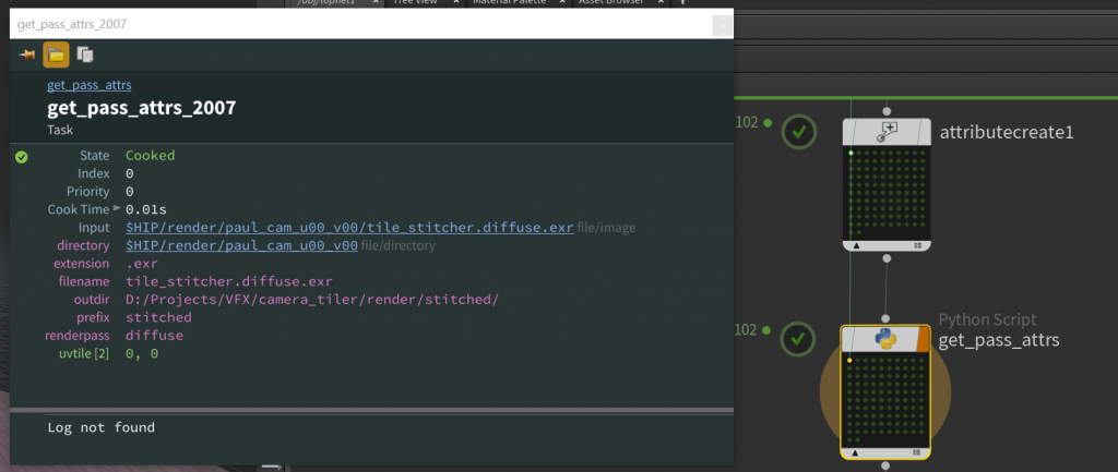
The attributes generated by our Python script.
Notice anything missing? We don’t have a defined output attribute anymore. This is because… reasons? I don’t really know, honestly, but because we didn’t explicitly tell this Python TOP to set an output attribute, it just up and vanished. You might not think much of this because it’s practically invisible, but many TOPs expect you to have these inputs and outputs defined or else they won’t work at all, and give you incredibly confusing errors as a consolation prize. To prevent this you need to enable Copy Inputs to Outputs on the Python Script TOP. It’s (of course) not the default, so if you fail to enable this, all hell will probably break loose downstream.
Computing the sort order
Not to get ahead of ourselves here, but we’ll be using ImageMagick to stitch the tiles together via the montage command. You’ll need to install it if you don’t have it already… don’t worry, it’s free. There’s a built-in ImageMagick TOP that will dispatch the command for us, which is great, except that it expects your images to be ordered left to right, top to bottom. Our UV tiles are ordered left to right, bottom to top. We essentially need to “flip” our tiles along one axis or the other. In this case, I’m going to flip our tile order along the U axis, and then sort in descending order.
To flip the tiles along U, we need to know our maximum U value. In SOPs we could easily get this using Attribute Promote. Our closest equivalent in TOPs, confusingly enough, is to collapse all our workitems into a single partition using the Wait For All TOP, and tell it to merge our uvtile attribute in “Maximum” mode. Then use an Attribute Create TOP to create a new integer attribute, maxu, based on the value of @uvtile.0, which is a shorthand for the first index (u) of our uvtile attribute. Then we’ll copy this attribute from our single partition back to all of our workitems. By default, Attribute Copy TOP will copy based on index, so a single partition will only copy to the first workitem found. You have to enable Copy Attributes from All Work Items to remedy this.
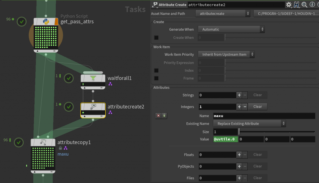
The network for computing the maximum U tile value, which we’ll need for sorting the UV tiles for ImageMagick.
Oh, and another gotcha, which TOPs seems to be full of… by default, the Wait for All TOP will build its partitions when workitems are generated. But we don’t have any idea what our uvtile attribute values are until the workitems are cooked. So the partition generated by Wait For All will just say our maxu attribute is zero, because why wouldn’t it be zero? You have to go to the Advanced tab of Wait for All and tell it to Partition When Input Items are Cooked, and then it’ll give you the right answer.
Under the hood, TOPs is doing this in order to minimize the number of dynamic workitems it generates. It prefers static workitems, meaning it can know from the beginning exactly how many tasks will be generated by each TOP, and so it can intelligently dole out resources to each dependency chain created by all of these tasks. There doesn’t seem to be any easy way, though, to automatically tell TOPs that you’re creating or updating attributes, so if you know that you’re analyzing existing task attributes in order to make a decision later on, you’re probably going to have to set your “Generate When” or “Partition When” attribute to run when items are cooked. TOP nodes operating dynamically will display a fancy little purple badge next to them so you can know that TOPs is angry with you for not using static workitems.
Now we can actually create our sorting attribute. This is where UDIM-like syntax would come in handy instead of our bootleg _u##_v## syntax for labeling tiles, because we want to iterate along tiles in the U direction for each V tile value. Let’s just use another Python Script TOP to generate this:
u = work_item.attribValue("uvtile", 0)
v = work_item.attribValue("uvtile", 1)
maxu = work_item.attribValue("maxu", 0)

sort_attr = work_item.addAttrib("sortorder", pdg.attribType.String)
value = "{:02d}_{:02d}".format(v, maxu-u)
sort_attr.setValue(value, 0)
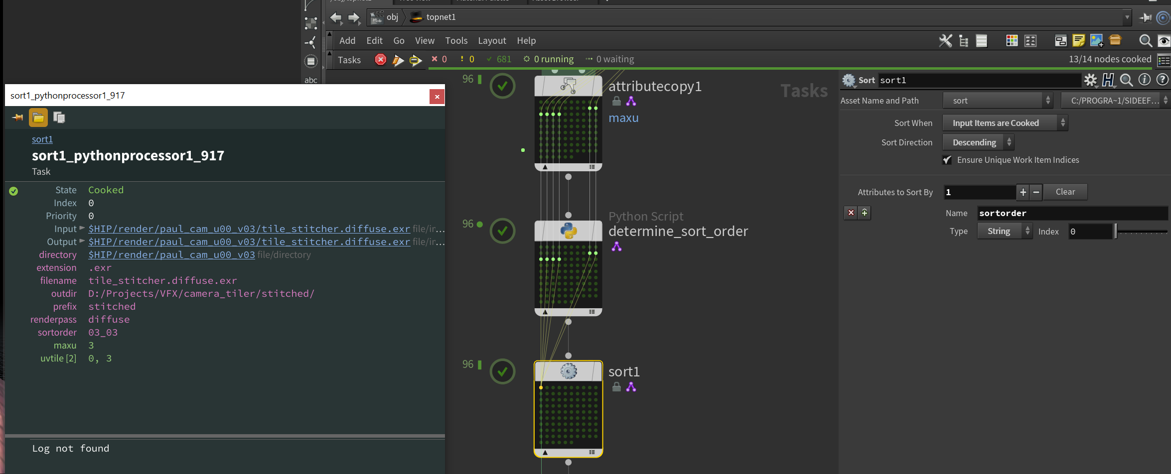
We’re creating a string to sort by, except we’re leading with V instead of U, and we’re flipping U by setting the sort attribute’s string to maxu - u. This makes all of our tiles sorted in reverse order, bottom to top, right to left. Oh, and don’t forget to Copy Inputs to Outputs again! Otherwise everything will inexplicably fail, like you’d expect a TOP network to do.
Now we can use a Sort TOP to sort all of our inputs based on the sortorder attribute we created in that Python Script TOP. We’ll sort in descending order, which flips our order entirely backwards, back to the proper order we need for ImageMagick: top to bottom, left to right. Since we’re depending on an attribute that doesn’t get computed until after the workitems are generated, we need to change the Sort When attribute to Input Items are Cooked, making this TOP also dynamic. With this Sort TOP cooked, you should see that your first tile will be in the top left, so u=0 and v=whatever your maximum v is.
Can we please be excused?
No. You came here for punishment.
We’re almost done, though. With all of these attributes generated and our workitems sorted into the correct order, there’s just two operations left. ImageMagick TOP expects a list of images to tile, and we want to make one image per render pass. The Partition by Attribute TOP will handle grouping our images based on our renderpass attribute. Set Partition By to Distinct Attribute Values and we’ll get one partition per unique value of our attribute. Again, we don’t know what these values are going to be until our earlier TOPs are cooked, so we have to set Partition When to Input Items are Cooked. Get used to doing this a lot.
Generate this node and you should see one partition per render pass created. If you take a look at the attributes, note that Output appears as a list of files. This is why we needed to be so careful about Copy Inputs to Outputs earlier in the workflow… the ImageMagick TOP expects an Outputs array of files to process. Without it, it’ll do nothing, and probably not bother to output a useful error for you either. This is what you deserve for using TOPs.
Finally, the ImageMagick TOP. The Output File Path is the first thing to configure. We want one file per render pass, and we already made all these nice prefix and outdir and renderpass attributes, so let’s just use those. In a rare case in which TOPs acts like the rest of Houdini, you can just use these attributes like you would any other attributes when creating the output string: `@outdir`/`@prefix`_`@renderpass.exr` will do the trick.
There’s some other ImageMagick-specific flags to set… the Background option should be set to None in order to preserve the alpha channel of your beauty pass, and it’d be smart to compress your output images, so create an extra argument named compress , the Argument Source to Custom Value, and the Argument Value to DWAA. This will keep these giant file sizes a bit more manageable.
One last thing before we run this monstrosity. TOPs can sometimes be pretty smart about how it divides up resources on your system, but when we’re dealing with writing absolutely tremendous images to disk, it’s best not to take any chances and melt the system. The default TOP scheduler in any new network, localscheduler1, is going to try to tile up every pass simultaneously. If your images are large enough, this will nuke your system. To prevent this, you can create another Local Scheduler, and set its Scheduling mode to Single. This will run only one tiling job at a time. Then set the Top Scheduler Override parameter on ImageMagick to this new scheduler’s path.
Okay. Set the Output flag (the orange flag) on your ImageMagick TOP, and either right-click > Cook Selected Node, or hit the little orange-and-white play button at the top of the node view to execute the output node.
This will rearrange our messy input tiles from this incomprehensible mess:
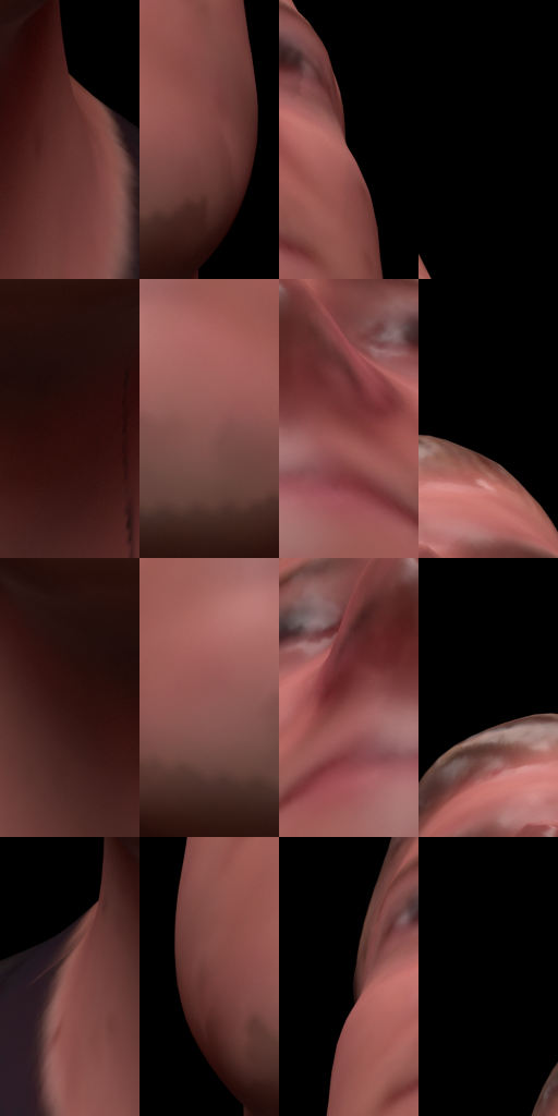
To this lovely look up digital Paul’s nose:
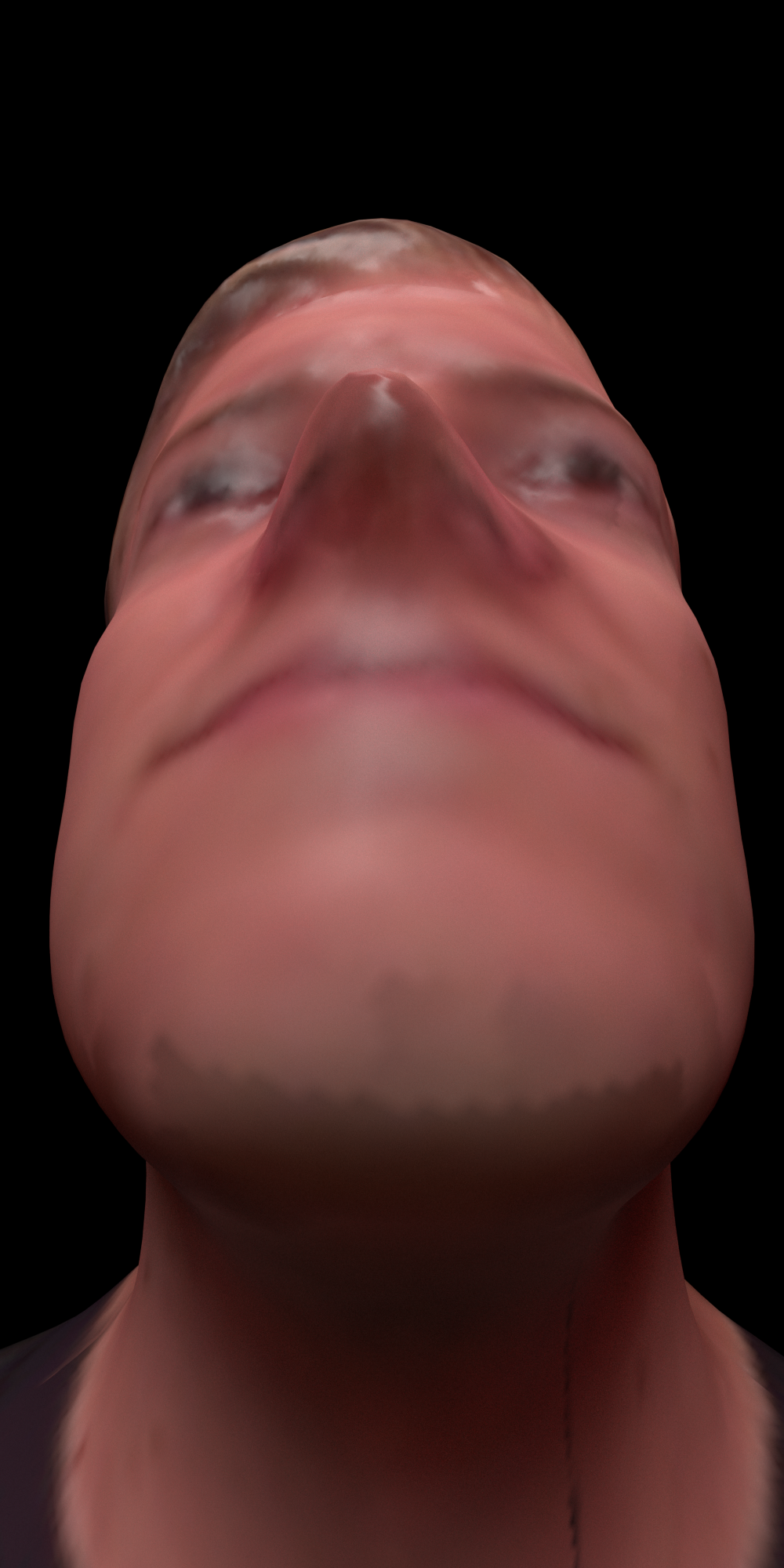
Please, make it stop.
That’s all for this project! I suffered for days trying to put this together, so I hope you all at least suffered (slightly) less reading through it. I’ll probably wrap all this up into some kind of neat HDA eventually, but for now I’m way too tired to be bothered, so enjoy your tiled renders! Special thanks to Jeff and Paul from SideFX for their TOPs help (and Paul’s lovely mug), and Adrian R. for his notes on camera slicing.
For reading this far, you get a present: the hip file. Enjoy!
11 Comments
Tim · 03/10/2021 at 05:05
Amazing work! I’m currently in the process of rendering out a 16ker and was about to do this manually. Thank you so much.
Just so you know, in your command to generate the passes/cameras you swapped out a “/” for a “_”. for the camera argument.
You wrote:
tile_camera(“/obj_cam1”, “/out/Redshift_ROP1”, 4, 4, “/obj/CAM_TILES”)
Thank you again!
toadstorm · 03/12/2021 at 15:15
Thanks for the correction!
TL · 01/17/2022 at 03:16
For those who are following the steps on this wonderful write-up and wondering why their filename attrib is missing the extension (.exr), there is a simple tickbox in the initial file pattern node called “Include Extensions in Filename Attribute”. Could be new in Houdini 19, not sure.
TL · 01/17/2022 at 03:29
Also for those who are struggling because their render passes file names have multiple dots in them, I devised this and found it to be functional.
splitbydot = re.split(r”\.”,work_item.attribValue(“filename”))
and instead of setting the value with passname, we simply do
pass_attr.setValue(splitbydot[-2])
Hope this helps someone out there!
Mark · 07/19/2022 at 15:16
Any help for those of us using C4D and Redshift? I can’t seem to get Deadline running and would like to try something like this. Your dedication is impressive. Thanks.
toadstorm · 07/19/2022 at 15:20
I don’t know any quick way of translating all this PDG hell I went through from Houdini to C4D… there’s no equivalent unless you’re going to code the entire process yourself in Python. Totally doable but way beyond the scope of this article.
If you have access to Houdini you could write your entire scene out to .rs, then load it into Houdini using the proxy loader and render using the method outlined here. You might need to export your camera separately as Alembic so you could split it into tiles, but the rest would work as described here.
JuanPi · 01/08/2023 at 22:09
Once again, you’ve saved my life in ways I never figured out I’d be needing in the future ! It’s my first time being forced to render a gigantic image for prints, and this post came as a perfect lifeboat since luckily I’m also using Redshift. Perfectly explained despite the overall complexity of the subject.. I would have never been able to come up with Python scripts like that. Bravo !!!
MD · 02/02/2024 at 20:44
One note .. those not wanting to go through this nightmare of PDG … though very cool … you can just stich your tiles in nuke.
MD · 02/02/2024 at 20:45
Oh … and i almost forgot .. this is one of the most generous offerings i have seen in this community… thank you so much.
Jay · 03/07/2024 at 03:41
I used the Rener tile preset, but used a standard camera (not a redshift one) as the reference camera, but in a RS scene, added a RS render tag to the Render tiles preset cam, and worked a treat, I guess it shouldnt work, but it did for me.
Ganesh · 10/18/2025 at 02:31
Even in 2025, this is the only post that helped with rendering the tiles.
Is it possible to render multiple redshift render nodes without changing the name in the python source editor for each?