I’m trying to push myself a little harder into the promised land of real-time 3D content, and as someone who is used to having at least a few minutes to render each frame, it is a real kick in the crotch to have to get things rendering at around 90 FPS instead. My current job involves a lot of VR prototyping, but the focus there is more on UI and UX than it is on graphical fidelity, so until now I haven’t really tried to push myself into generating VR content that actually looks halfway decent.
I’ve decided that my first big project is going to be constructing an environment and optimizing it to run for the VRChat platform. I figure it’d be a good way to practice both content creation and optimization, especially if I’m to ever make this environment compatible with the Quest, and making it run in VRChat means that I can actually interact with people in it and share it a little easier.
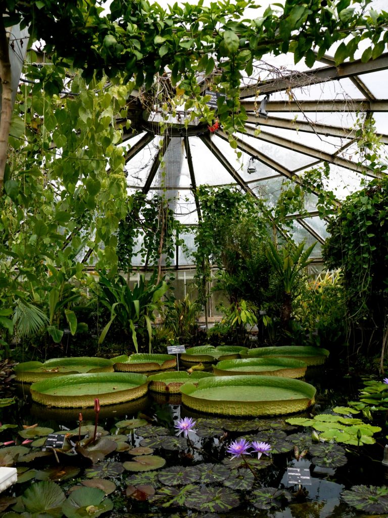
My goal is to build a conservatory (the plants kind, not the music kind) because I like green spaces and growing plants in 3D. This is also sure to create exciting technical nightmares for me because plants are hard to optimize and transparency cheats are a real performance killer. Something along these lines, but with a little more space to move around:
A quick disclaimer: I’m posting this as part of my learning process. My background is in film and commercial visual effects, not video games. I’m an idiot in general, but I’m especially stupid when it comes to real-time graphics, so there will likely be some flaws in my workflows here. Feel free to yell at me in the comments.
Making it rain
Anyways, because I clearly like making things hard for myself, I decided that it definitely should be raining outside in this environment, and that means I needed to build a shader that looked like rain streaking down glass. Now, normally in film or commercial production, you’d throw a few particle systems together, mesh them, put a water shader on them and get some nice refractions and call it a day. It takes a while to render, maybe, but it’s fairly straightforward stuff for an effects artist to do. Not so in real-time! While it is possible to do particle simulations in real-time, trying to simulate all these rivulets and raindrops hitting the glass panels would likely be too expensive to calculate to keep up the kinds of framerates you’d need in VR.
Another option would be to use an off-scene camera that’s rendering a small-scale particle simulation by itself, and storing that render to a buffer. In Unity, this is called a Render Texture. This image could be processed to act a little like a normal map and then used to distort the background. However, this means you need to have a prefab set up and configured in any given Unity scene you’re using the shader in containing the particle simulation and a camera to render it, and that extra render takes up valuable system resources you could be spending elsewhere. This Youtube tutorial describes this workflow a little better.
There was one other option I’d considered that looks pretty good in practice, and the technique behind it is genius, but it’s implemented entirely in code and looked like it would have been extremely difficult to art direct, at least for someone as dumb as me. The results are pretty great, though, and the tutorial is worth watching either way.
Edit: Andreas Glad informed me that particles simply spawned on the surfaces would actually likely be cheaper than the shader method I ended up with, because there would only be overdraw where the particles actually existed rather than across the entire glass surface. I’m still going to stick to the texture method for now, but it’s good to know that particles alone could work for this.
The method I settled on is partly adapted from this very informative little tutorial that describes a few shader tricks like “alpha erosion” that are essential in creating the raindrop impact effect. This stuff is probably painfully obvious to anyone who’s done real-time effects work, but for someone not accustomed to the hacks and tricks endemic to real-time, it’s great to see it explained so thoroughly. The final effect uses just two static texture maps: one for the raindrops, and one for the rivulets. All of the animation is handled by the shader, so it’s pretty cheap in comparison to some of the earlier methods. Here’s a test environment showing the result, with my dumb head in VR as the camera:
Unity rain shader from Toadstorm Inc on Vimeo.
Raindrop textures breakdown
The two texture maps that are used to create the effect are fairly simple. I put them together in Substance Designer. The first one is for the raindrops effect. Here’s what the texture channels look like:
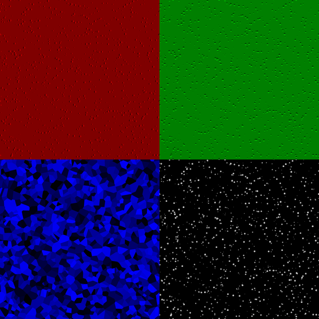
I scattered a slightly distorted paraboloid shape using an FX Map, then ran it through a Normal operation to get the red and green channels suitable for distorting the final image in the shader. The smaller droplets are also dimmed proportionally to their scale; this means that they’ll have less “height” than the bigger droplets. (This is used later to allow the shader to determine how “heavy” the rainfall is.) This part is pretty straightforward in Substance Designer… just scatter the shape and get normals from it. The alpha channel is simply the original image without the Normal operation. The gradient in that scattered shape is used later in the shader to create the erosion effect.
The blue channel was the most involved bit, but still not too crazy. I used the exact same FX Map to scatter a tiny square in place of the droplets, then used a Pixel Processor to create a copy where all of these squares were white (using ceil() on the input). These two images were input to a Distance node, which resulted in the voronoi-looking noise going into the blue channel. This value is used in the shader as a time offset; essentially adding the value of the blue channel to the scene time in order to randomize the appearance of the raindrops.
Raindrops shader network
The raindrop material itself is just a Unity Standard Surface set to the Transparent Render Queue (so that it you can see through it). If you don’t need any kind of lighting effect on the glass, you could set the lighting model to Unlit instead of Standard and it would work fine; all the magic here is being piped into the Emission channel of the shader.
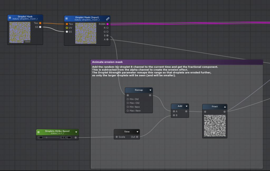
Now things start to get a little hairy. First, the raindrop impact times have to be figured out. The blue channel value is added to the current time, and then the fractional component of the result is written to the buffer. This means that the resulting values for each pixel will count up from zero to one (black to white) and then loop back to black, offset in time by the random value from the blue channel that exists per-droplet. The shader network looks like this:
And the resulting value applied to a sphere:
Next, this looping timer value that was just created needs to be subtracted from the alpha channel. Remember that the alpha channel is a gradient resembling a height field, where droplets are white in the middle and black on the outside. If the timer value is subtracted from these gradients, you can imagine that the darker values will dip below zero (black) first, and then the lighter values towards the centers will follow. The final step is to make any pixel that’s even a tiny bit white (greater than zero) into pure white, using the ceil() function. This is the secret behind alpha erosion. The result of the operation looks like this:
It’s a little janky, but when it’s being used as a mask the artifacts will be a little less apparent. In later versions of this shader I’ll separate the voronoi cells so that the edges don’t cut near any droplets.
Now this black and white mask can be multiplied against the red and green channels that will act a little like a normal map:
The final little bit of magic for the raindrops part of the shader involves something called a grabpass. (In Unreal Blueprints I think the equivalent is Scene Color.) What this function does is capture everything behind the currently shaded object (assuming that it’s transparent!) and store it to a texture. The Grab Screen Position node first gets us the normalized coordinate space of our camera. The red and green values shown above are remapped from a range of (0,1) to a range of (-1,1), then multiplied by a “Distortion” input parameter with a fairly small value (0.02 is a good start). The result is then added to the Grab Screen Position coordinates. Finally, the result is connected to the UV coordinates of the Grab Screen Color node, which fetches the grabpass. The result is that the image behind the glass is slightly distorted by the shape of the raindrops:

It’s a decent start! It really does get the impression of raindrops across, especially in VR, and it’s just one texture map so far. Here’s the complete shading network at this stage:
Next up are the rivulets, which are a bit trickier to wrap your head around, but there’s some familiar concepts for those of you who have used Houdini before…
Rivulets shader network (part 1)
One of the most important qualities of the rivulet movement is that it isn’t perfectly uniform… droplets will zigzag slightly and sometimes hang briefly in between bursts of movement. It’s hard to nail this kind of motion perfectly without using a particle system, but you can approximate it by using what’s called a flow map.
Flow maps allow you to distort an existing texture by using two channels of some other texture to offset U and V. By looking up the values of this distortion map and then adding them to the UV coordinates of the actual texture over time, you can create something like a scrolling effect that can actually warp in different directions, like a river flowing. Here’s a video example of what this technique can accomplish, from an old flow map demo by Hywel Thomas:
Here’s a more detailed tutorial on how flow map shaders work by Gary Dave: https://www.artstation.com/artwork/BmrQyz
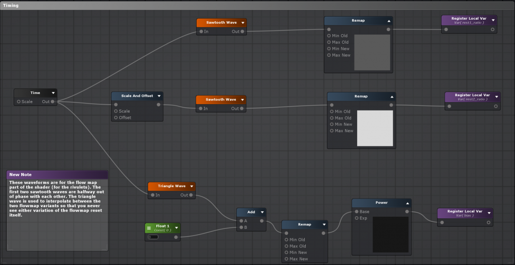
The catch to this technique is that if you simply add these values to your UV coordinates and let it accumulate over time, eventually the distortion will be so great that your texture completely falls apart. The way to avoid this is by resetting your UV coordinates periodically. However, just doing this blindly would cause the texture to visibly “pop” each time the coordinates are reset. Instead, you smooth out this effect the same way you make a lot of different things loopable: you take the same effect twice, staggered at two different time offsets, and interpolate between them. If that’s hard to visualize, take a look at this graph. The two offset distortions are the blue and green waves: they’re the same exact function, just offset in time. (The waveform is a “sawtooth” wave, meaning it simply travels from zero to one, then immediately loops back to zero.) The red wave is the weight between them: when red is 1, the output will be fully biased towards the green wave, and when red is 0, the output will be fully biased towards blue. If you look carefully, you’ll notice that this means you’ll never see the blue or green wave when it’s snapping from zero to one.
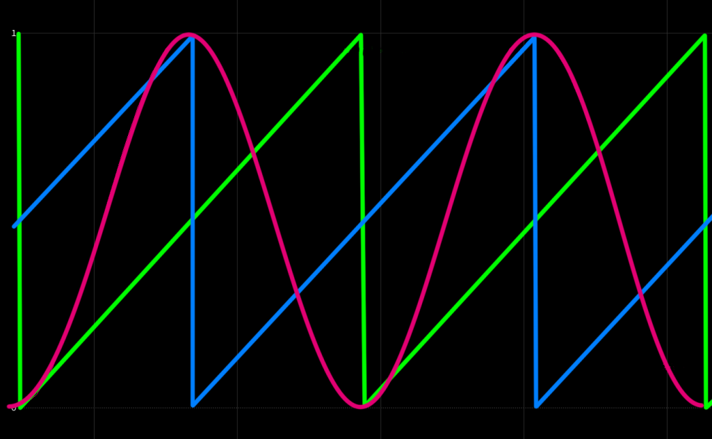
If this graph doesn’t clarify this concept for you, and I don’t entirely blame you, here’s what the three graphs look like as animated values:
If this concept seems a little bit familiar to you Houdini users, it’s because it’s basically the same as dual rest fields in Houdini. You push two UV fields through your smoke (or fluid) velocity field, reprojecting them at a set interval out of phase with each other, and blend the weights between the two so you never see the reprojection happening. It’s a very versatile trick!
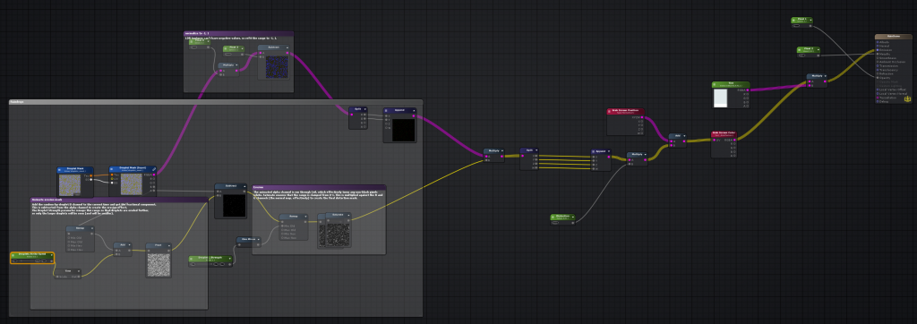
Before we move onto the texture, here’s what these timing channels look like in Amplify:
Rivulets texture
Now that we have some theory out of the way, here’s the rivulet texture map generated in Substance Designer, with the channels separated:
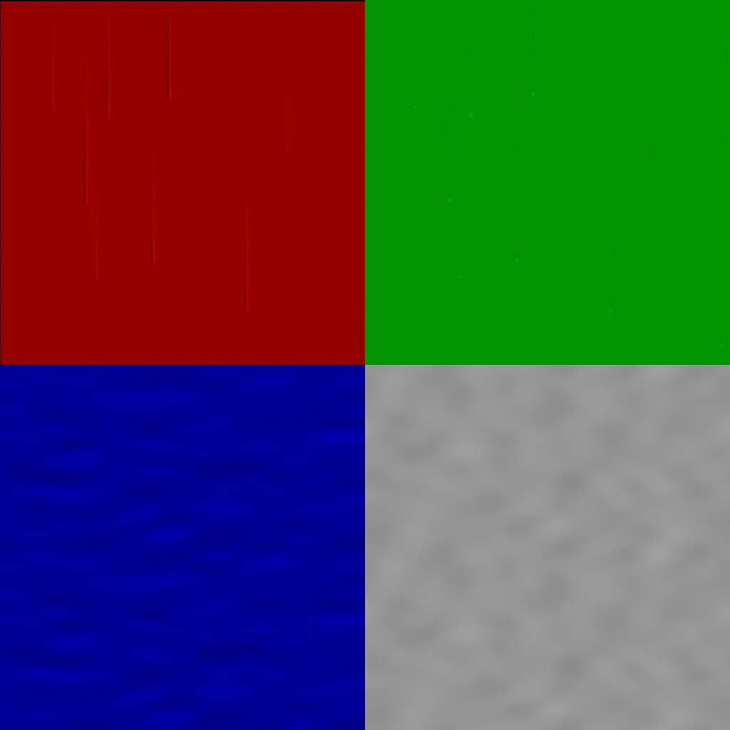
The red and green channels are more or less the same as what we were doing with the raindrops texture earlier in this post. We’ll use the channel values to distort the background texture. The blue and alpha channels are the flow map texture, generated from some simple Perlin noise. Blue distorts the rivulets horizontally, causing them to zigzag, and Alpha distorts them vertically, which creates the impression of their speeds changing a bit over time as they fall.
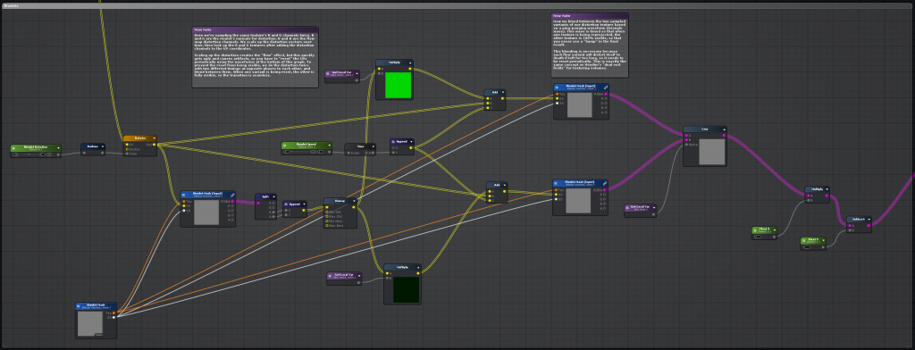
Rivulets shader network (part 2)
Now we actually have to use these color channels and fancy timing channels to distort our texture lookup (for the red and green channels that describe the rivulets themselves). We’re going to do this process twice, once for each variant of the distortion process. The process is the same for both: get the value of the timing channel (the sawtooth wave) and multiply the texture map by this value. Then, add the B and A channels to the existing UV coordinates, and use the result to look up the original texture again. Finally, we take both of these variants and blend them together with a lerp function, using the “weight” channel (the red waveform in the earlier graphs) to blend between our two distorted textures. Here’s what that network looks like:
Finishing up
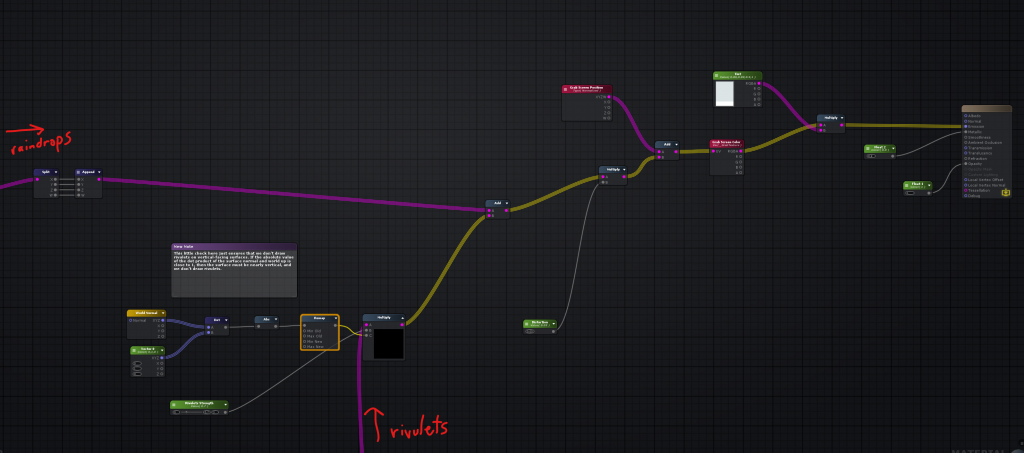
Now that we have our rivulets, we can just add our resulting R and G channels to our raindrops mask from before. However, if we want this shader to be especially versatile and work on glass that’s facing in any direction, it’d be a good idea to make it so that we don’t see rivulets on surfaces parallel to the ground, since gravity isn’t going to be pulling those raindrops into rivulets. This is a pretty simple thing: all we need to know is the world normal of our surface. Assuming that world “up” is {0,1,0}, we can determine how “horizontal” a surface is by taking the dot product of the surface normal and the world up vector, and taking the absolute value of the result. If a surface is entirely parallel to the ground, the absolute value of the dot product will be 1, and if it’s entirely perpendicular to the ground (like a standing wall), it’ll be 0. Reverse this value using a Remap or similar function, and we can simply multiply our distorted red and green rivulet channels by the result, naturally masking out the rivulets as surfaces tilt towards horizontal. Then this result is just added to the raindrops channels, for use with the grabpass setup described earlier. Here’s the graph for this part:
And finally, the output on a sphere. The camera is placed slightly underneath the sphere looking up so that you can see the rivulets being masked out towards the top and bottom:
It’s not perfect, but it does a good job creating the impression of rain streaking down glass, and more importantly, it’s fairly cheap. I’ll still need to do some more benchmarking and testing to see if it’ll run on a Quest 2, but it certainly has a better chance of meeting framerate requirements than anything involving a Render Texture, and it requires less setup than a particle system.
Hope this was helpful to anyone who’s also trying to make the transition from offline graphics to real-time!
Update: The shader is now available for download on Github here: https://github.com/toadstorm/RainyGlassShader
Part 2 of this series talks about the overall construction of the architecture, including the texturing process and some of the other (and much simpler) effects shaders involved.
Part 3 talks about the procedural generation of the plants, and some optimizations to keep the draw calls to a minimum.
9 Comments
ethan · 12/23/2021 at 19:45
Looks really nice! Did you ever end up testing it on a quest? Seems like using frame grab might prohibit it working very well on that platform?
toadstorm · 12/23/2021 at 19:50
Thanks! Yeah, this won’t work at all as-is on a Quest because of the grabpass, but I recently ran into an Amplify shader published by a prolific VRChat shader writer named S-ilent who solved a similar problem by grabbing and returning reflection probe lighting instead of the grabpass. I adapted her shader to use my rain textures… it doesn’t look quite as good as the PC VR version but it runs well! Her original shader is here: https://gitlab.com/s-ilent/fake-glass
ethan · 12/24/2021 at 12:00
I actually had just found that while doing the searches which brought me to your page :) It currently gives me an error though which I added to the Gitlab. undeclared identifier (I don’t know anything about coding shaders I’m afraid) I had thought maybe it was because my project is URP. but I dropped the fake-glass into a built in project and it gives the same error.
uroboros · 04/02/2024 at 08:04
Hello, this is an amazing shader! I have a character looking at through this glass and and the drops near him reflects/refracts his model, which is annonying when the camera is moving. It would be best if the grab pass took only what is behind the glass, not what is in front of it.
Do you have some suggestion? If you have more info about the PC VR shader with your shader, please send me email! Thank you very much!
toadstorm · 04/02/2024 at 15:14
I’m glad you like the shader! I’m still kind of a shader scrub so I don’t have an implementation of the fixed refraction shader available for you, but I know it’s possible to tweak the effect by removing the distortion based on a depth/fog sample. Catlike Coding does a great job explaining it here: https://catlikecoding.com/unity/tutorials/flow/looking-through-water/
It does mean that you’d need to have at least one real-time light in your scene to trigger the depth pass calculation, which could affect performance on low-end hardware or in very busy scenes.
Kiwi · 01/26/2025 at 09:51
I love the shader, I tried to look at the GitHub, but it doesn’t show a downloadable file?
toadstorm · 01/26/2025 at 09:54
The shader and relevant textures are in the unitypackage file here, you can download it directly from GitHub: https://github.com/toadstorm/RainyGlassShader/blob/main/toadstorm_RainyGlassShader.unitypackage
irfan · 01/27/2025 at 00:16
Does it work for URP?
toadstorm · 01/27/2025 at 07:41
I haven’t tasted it in URP. Amplify supports both pipelines so I’m guessing it should work with maybe a few tweaks.