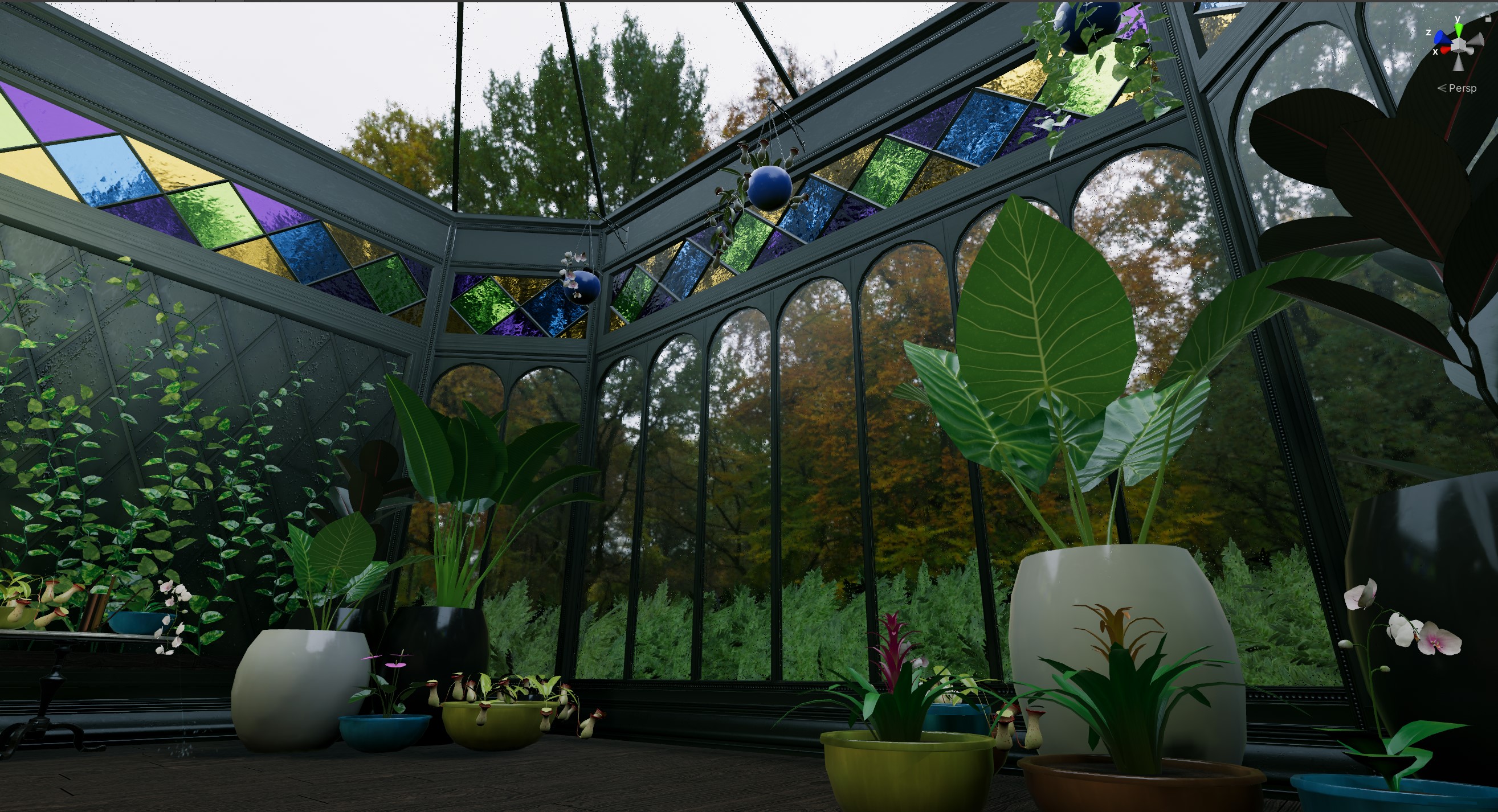
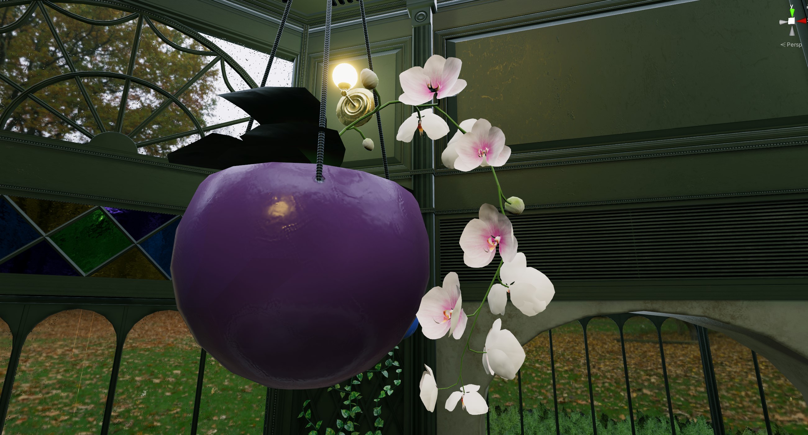
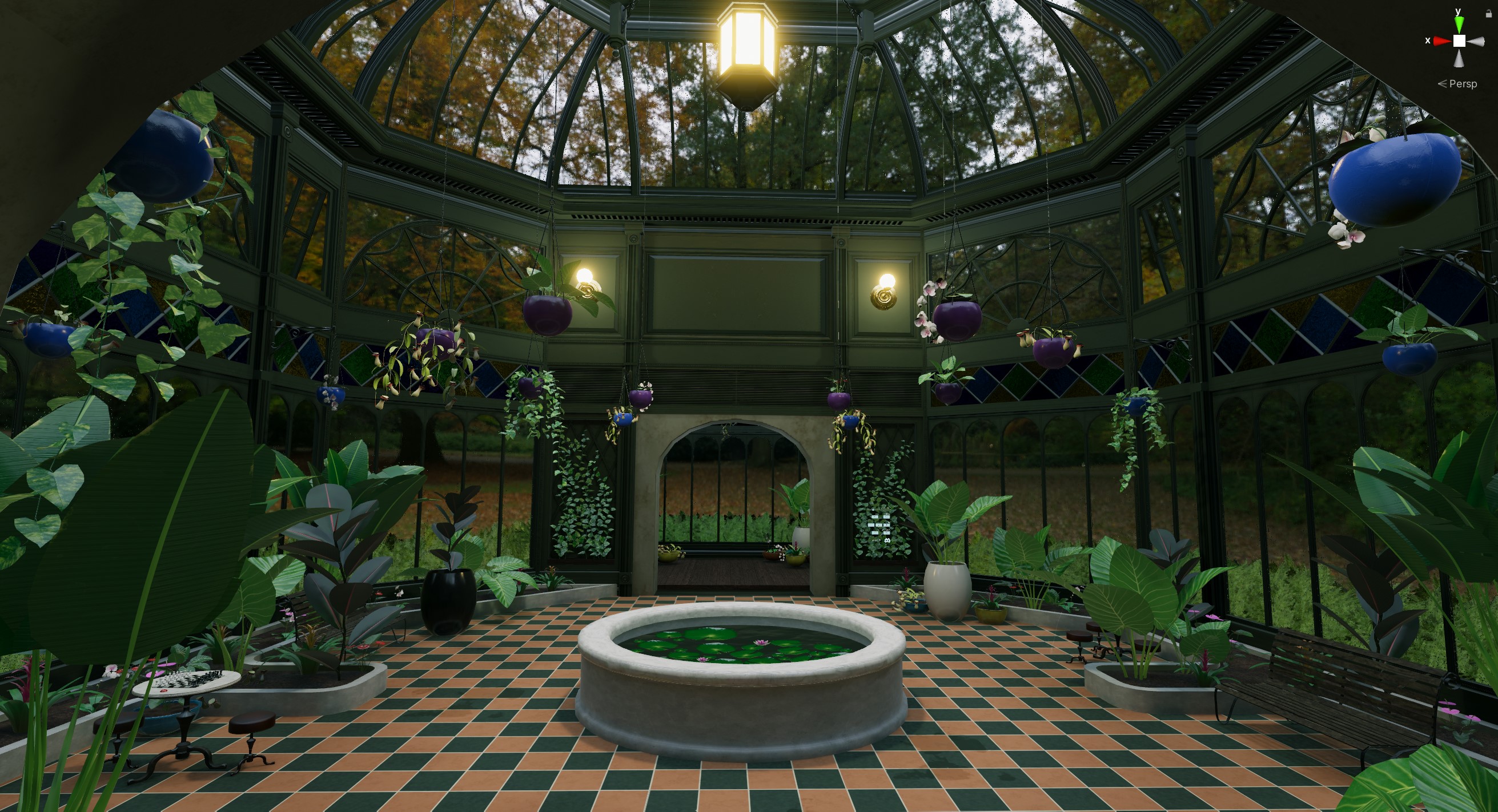
The big draw of The Conservatory, other than the very neat rain shader, is the plants. I spent a long time researching different candidate plants that would roughly fit into the same tropical environment, with a decent range of morphologies that would help fill out the space. That meant a few really enormous plants like the giant taro or “elephant’s ear” to carve out space, and smaller plants like the Nepenthes (pitcher plants) and Phalaenopsis (moon orchids) to fill in-between areas and add color. There’s a few creative liberties taken (I don’t think you’d ever want to place carnivorous plants in the same soil as 90% of these other plants), but overall I wanted the place to reflect real plants in a mostly believable environment.
Simple plant procedure
Most of the models were built using a somewhat standardized approach, using Houdini to handle all content generation aside from textures. I’d first build the major organs like leaves or flowers, and then build some kind of procedural system to handle the stems that would hold them. The organs could be slightly randomized in order to allow for some variety in shape, but in order to minimize texture requirements, they mostly varied in scale and orientation. Every flat shape like a leaf or flower was modeled as a flat shape, duplicated, flipped, and then merged to form a two-sided mesh before being warped and bent into the final shape. Early performance tests suggested that double-sided meshes performed a little better than fully two-sided shaders did, despite the extra polygon count, and it meant that I could use different texture maps for the front and back of each leaf shape. (The downside is that certain tricks for translucent leaves won’t work well without single-sided geometry, at least as far as I can tell).
Here’s the rough process for the Alocasia (giant taro) leaf shape. Most leaves in The Conservatory were built using this kind of template: start from curves, use Planar Patch From Curves to surface them, follow with Exoside Quadremesher to turn them into clean quads, then slice out a central shape to be formed into the stem of each leaf, create UVs, reverse and merge to form the backside, then warp into shape.
Stems were handled in a number of different ways, depending on the growth pattern of the plant. The Alocasia was pretty straightforward… just a cluster of stems coming out of the ground and bending towards the ends. This could be handled by something like L-systems, but those can get complicated very quickly. In this case I just scattered some slightly rotated straight lines in a tight cluster, then used the Guide Process SOP to bend them and add a little random noise. The tips of these lines were used as template points to copy the leaves to. The stems were then converted to geometry via the Sweep SOP and fused with the leaves.

The anthuriums (also called laceleaf or flamingo flower) were built using a similar process, just with a slightly more complex ruleset. The leaves of these plants tend to be a little heavy and the stems bend under their weight, but the stems with flowers (technically they’re called “spathes”) tend to not bend quite as much, at least in the reference material I had. To this end, the scattered straight lines for this plant were given about a 30% chance to become “spathe” stems, which made them slightly less bendy and gave their endpoints a different variant attribute for the purposes of copying spathes instead of leaves.
Finally, some random noise was applied to the point positions, to wrinkle the leaves and spathe slightly. I used MOPs falloff nodes (from my Houdini motion graphics toolkit) to localize the wrinkling to thinner areas outside the ribs of the leaves, and to prevent the ribs from not lining up exactly with the stems. MOPs falloffs are mostly just simple formulas that generate float values between zero and one in different preset shapes, useful for creating quick masks and gradients without needing to paint them manually. These values can be used to mask most nodes in Houdini, including the Attribute Noise SOP used for the wrinkling. They’re very versatile!
Once the leaves and stems were in place, the endpoints of the stems and matching endpoints on the leaves were fused and the normals recalculated so that the resulting geometry feels seamless.
Building plants parametrically like this is really important if you want to be able to quickly crank out lots of different plant variations. By adjusting a few random seed values early in the process, you can create enough unique plant models to prevent instances from looking too similar to each other when populating a world.
Phalaenopsis procedure
Of course, not all plants are this straightforward. The phalaeonopsis (moon orchid) was a much trickier build, both because of the complex flower structures and because of the way the leaves are positioned. This particular orchid has a tightly-packed series of spoon-shaped leaves stacked on top of each other near the ground, and then a long stem that branches out into the striking flowers orchids are known for. Like most effects problems, this was more easily broken out into several bite-sized steps that could be merged together at the end.
Base leaves
The leaves grow just above the ground, and they’re packed in pretty tight and immediately start bending, so the earlier approach wasn’t the best for getting the leaves in the right place. I still wanted to start by manipulating curves to form the “skeleton” of the plant, though, so I modified my earlier approach.
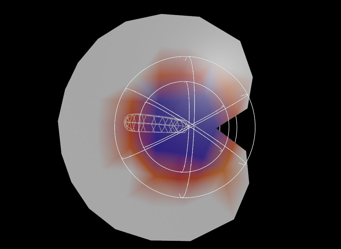
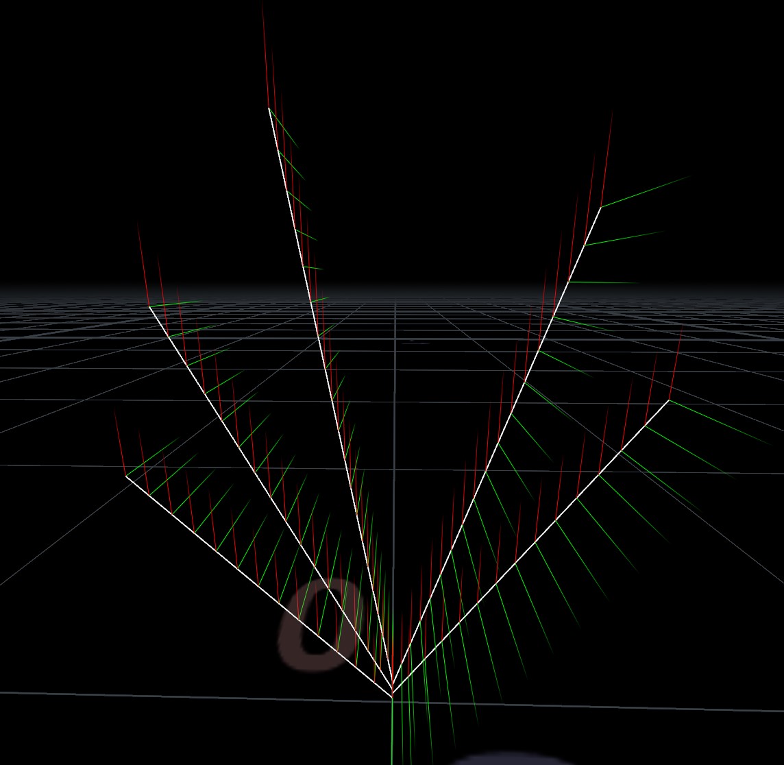
A tiny stem was generated as a straight line, and each point on the line was twisted using the Orientation Along Curve SOP so that the leaves would grow in opposing directions along the length of the stem. You can see the orientations in the following animation as little gnomons. I followed up by using MOPs Transform to rotate the stem points upwards, so that the leaves start with a pitch towards the sky.
Next, the lines that will be the skeleton for the leaves are copied to those points, and bent using a series of Guide Process SOPs. Guide Process Bend can read specific attributes to control the amount of bending and the axis to bend along, per-point. I wanted the leaf skeletons to bend downwards, so the axis to bend along had to be orthogonal to the direction of each line itself, and the world up vector. Imagine a line sticking out the “side” of each point along the skeleton lines… this is the axis needed to drive the bend.
Thankfully there’s a pretty easy trick to getting an orthogonal vector… the cross product. A bit of simple VEX on these points is enough to create the bend axis attribute needed by Guide Process:
v@bendaxis = normalize(cross(@N, {0,1,0}));
In this case, @N is the normal of each of those curves, which was earlier calculated to be the pointing direction of each curve via Orientation Along Curve. The resulting bendaxis attribute can be directly used to inform how each curve bends.
The higher-up curves needed to bend a little more than those below it. This was handled by computing a similar attribute, bendamount, based on the point number of each source leaf point (transferred across to the skeleton lines as the copynum attribute from the Copy SOP). A little more VEX:
 // this fetches the total number of points on the stem geometry
int copies = npoints(1);

// this maps each line in order to a 0-1 value, so the last line is 1.0
float u = float(i@copynum) / float(copies);

// this takes that 0-1 value and looks up a ramp control to determine the amount of bending per-line along the stem
f@bendamount = chramp("bend_ramp", u) * ch("bend_scale");
With that, the leaf skeletons can be warped in a way that makes them stack up nicely. The skeletons were then used to bend some basic template leaves (built like most of the previous leaf models) using the Path Deform SOP. For each curve primitive, the same template leaf was warped onto the skeleton curve via Path Deform, and the results merged together at the end (via a For/Each block). Here’s the whole process visualized:
Primary stem
The main stem of these orchids tends to grow straight out of the ground and then bend over towards the top. Sometimes there’s a bit of a bend towards the tip of the stem, almost like a shepherd’s crook shape. I got this shape through a combination of a simple L-system and a C-shaped curve copied to a few points along the stem (as attachment points for buds or flowers there) and to the end of the stem (for the crook shape).
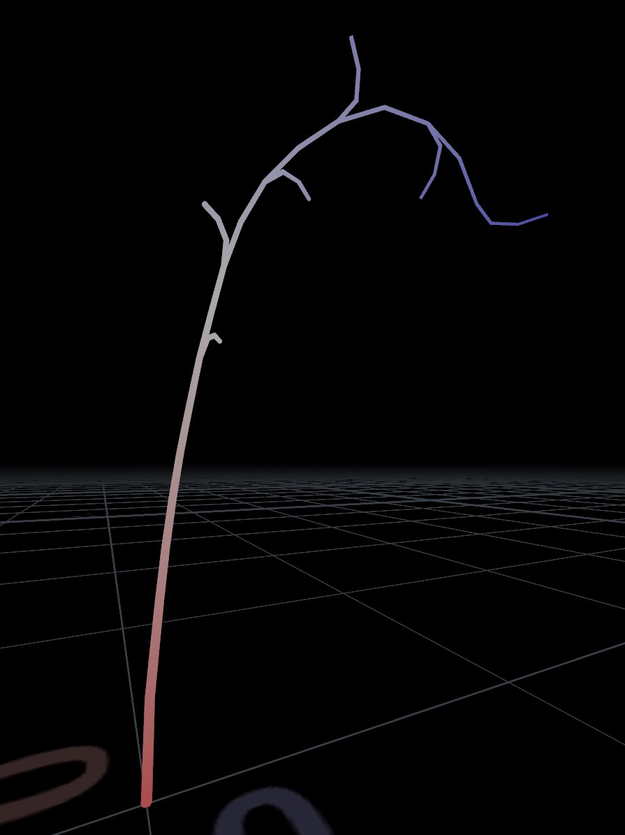
After the little C-shaped stems were copied to the main stem and fused, the Find Shortest Path SOP was used to compute the distance from root to tip for each endpoint. This value, cost, can be used to drive the thickness of the stem so that it naturally tapers towards each endpoint:
float maxcost = detail(0, "maxcost"); // promoted from cost to find the max
float u = @cost / maxcost; // another 0-1 ratio for a ramp control
@pscale = chramp("width_ramp", u) * ch("scale");
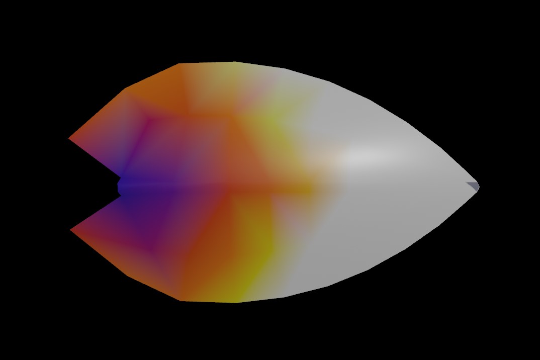
The resulting pscale attribute can drive a Polywire SOP, creating the actual geometry for the stem. Here the attribute is visualized as a ramp from red to blue:
The buds and orchid flowers were modeled separately the old-fashioned way, and aren’t really worth mentioning here. Because the flowers tend to open up towards the end of the stem first, I used yet another ramp parameter and some VEX to drive the likelihood of a flower being copied to an endpoint rather than a bud:
float max = detail(0, "maxcost");
float ratio = @cost / max;
i@variant = int(rint(chramp("bud_ramp", ratio)));
This variant attribute is used by the Copy to Points SOP to determine what geometry is copied to each endpoint. The ramp tapers from a 100% chance of a bud at the root to about a 10% chance at the tip. (It’s not really randomized in this example… you could add a little randomization by adding a bit of noise or some other random value to the computed ratio).
Wrapping this up then just involved merging all the various parts together and applying a bit of noise to the flowers to make them feel a little less stiff, just like in prior examples.
Optimization
After the plants were built, they were combined into “sets” in a separate Houdini geometry container so that the materials could be more easily shared. For example, one plant set contained the Phalaenopsis and the Nepenthes (pitcher plant). Because the leaves and flowers were all modeled separately and copied to form the final plants, the UVs were generally predictable and the layouts could be the same for any variant of the plant; the only UVs that changed were the stems, which were unfortunately a little messy but in general weren’t too noticeable.
For example, here’s the final UV layout for the plant set containing the orchid and the pitcher plant:
This is just basic material atlasing… combining multiple objects together into one texture set so that they can share materials, resulting in less materials (and less draw calls) during runtime.
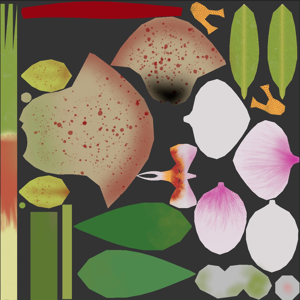
Another little trick is visible in a different plant set, containing the rubber tree, giant taro and anthurium:
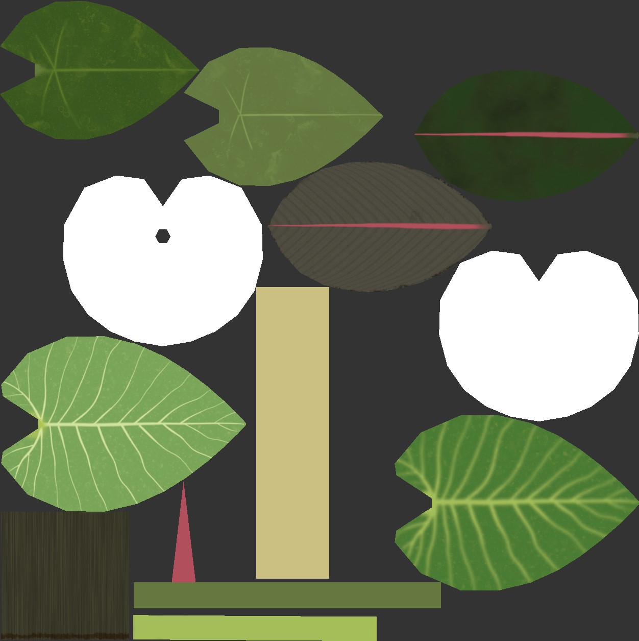
The brightly-colored spathes of the anthurium can come in a pretty wide variety of colors, but I didn’t want to waste precious texture space on these possible variations. Instead, the base color map for the spathes was left white, and vertex colors were used in the model variations to create the different colors by simply multiplying them against the base color map. Other plants had much more subtle variations in their vertex colors to make each leaf a slightly different shade of yellow or green. Texture space is always at a premium (especially when your world size needs to stay below 100 megabytes for Quest compatibility), so any little trick that can help minimize the amount of textures you need to use is worth looking into.
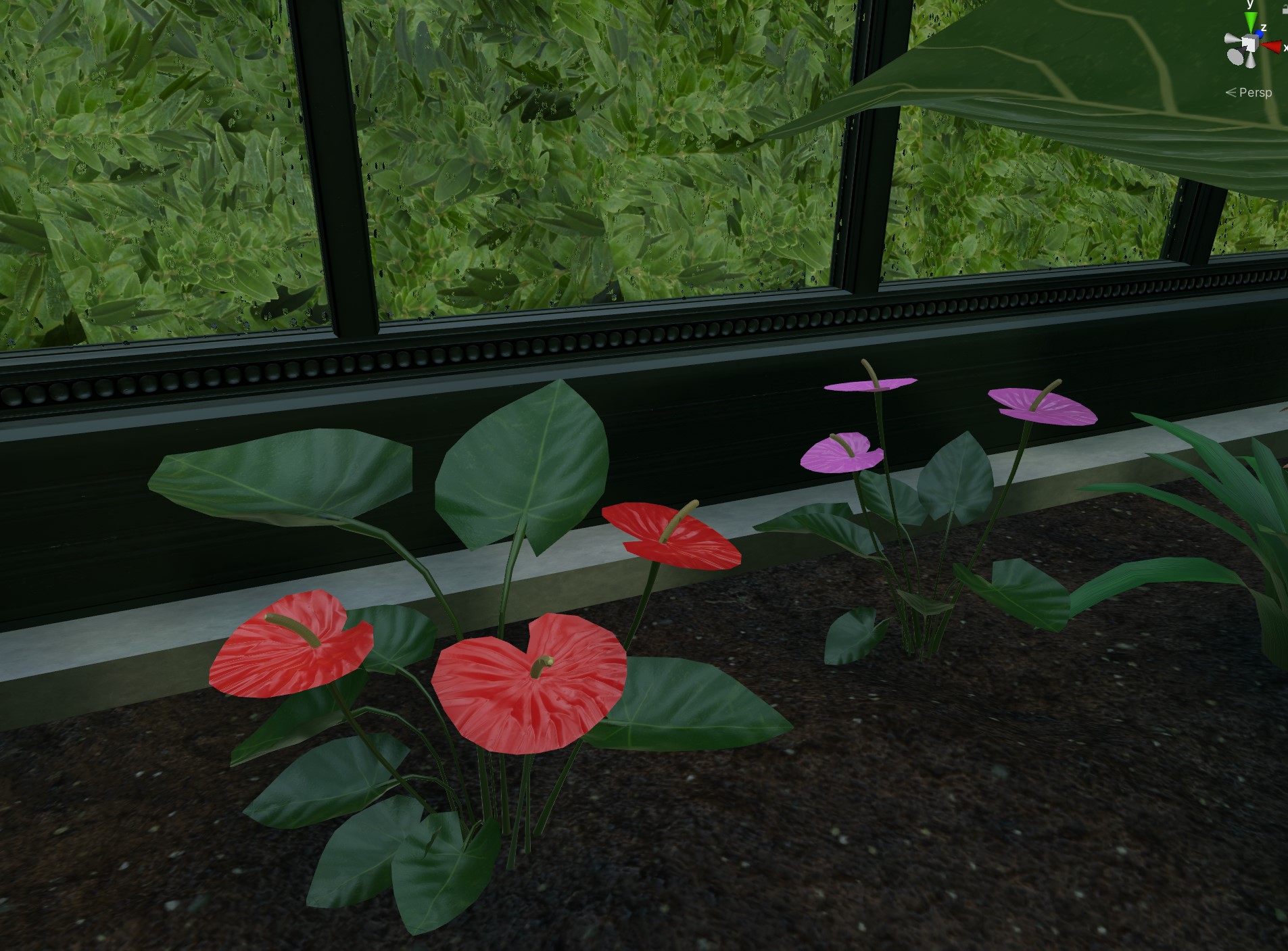
The other major optimization applied to these plants is the use of GPU instancing. Because the plants are all copies of the same handful of base models (about two per plant type except the pothos vines), they’re prime candidates for instancing. Simply copying the models around the scene and checking “Enable GPU Instancing” on the material is enough to let Unity handle everything for you, as long as the models aren’t set to be static for batching purposes! GPU instancing massively reduces draw calls in scenes with lots of duplicated geometries (like plants) and is essential to getting a decent framerate, especially on mobile hardware. Without it, there’s no way I’d be able to fill out a whole room with this amount of geometry.
One other thing worth mentioning: There are a lot of incredible tropical plants out there that I could have filled this space with, but the ones I selected were very carefully picked to be good candidates to build without cutout shaders of any kind. This means some of the leaves show some faceting along the edges, and the polygon count might be a little higher than I’d otherwise like, but GPU instancing handles this well. Cutouts (and transparencies) are expensive to draw, and can be crippling on mobile hardware. I decided to just avoid it altogether in the interests of performance and Quest compatibility.
Next up
Sorry this took forever to write! MOPs and my day job keep me pretty busy. The next (and probably final) post on this project will be about some of the smaller details: the wobbly liquids shader found in the teacups and the secret bar, some of the tricks involved in the control panel, the koi in the pond, and a few other tiny little things that help bring everything together and make it feel more like a real place.
In case you missed them:
Part 1 of this series talks about the fancy rain shader used on all the glass surfaces.
Part 2 of this series talks about the overall construction of the architecture, including the texturing process and some of the other (and much simpler) effects shaders involved.